Instead of placing cross sections by hand or using a boundary,
it is also possible to import them directly from an AutoCad DXF drawing.
To use this method, please make sure you use a separate layer in AutoCad to store these lines.
To start importing the line data used to create sections, select the "Generate sections from DXF..." option by right clicking
the "Sections" folder in the project view. If the project view is not visible, you can show it by selecting "Project Explorer" from the "View" menu.
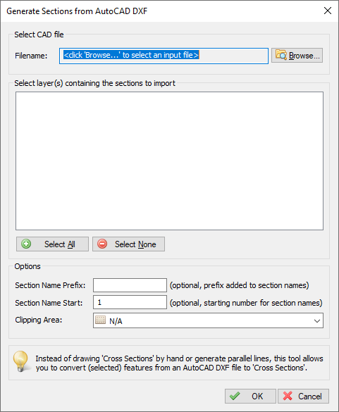
The generate cross sections from AutoCAD DXF file importing tool
First, you have to click the "Browse..." button to select an AutoCAD DXF file. If your AutoCAD file is saved in the DWG format, you can export it to DXF by using the 'DXFOUT' command in AutoCAD.
When a valid file has been selected, the layer names will be loaded and displayed in the dialog.
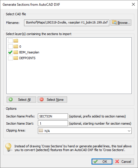
Select the AutoCad layer(s) that contain the cross sections
After the AutoCAD file has been loaded, you have to select one or more layer(s) containing the line data to be used.
You can select one or more layers, please note that only 'LINE', 'POLYLINE' and 'LWPOLYLINE' entities can be converted into cross sections.
When the selected layers do not contain lines, or unsupported line entities , the following error message will be displayed when starting the import process:
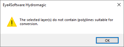
When the selected layers do not contain lines in the correct format, Hydromagic will notify you.
Normally, the name of a cross section consists of a number.
To provide more clarity about a cross section, or to group them, the section number can be preceded by a short text. This setting is optional.
All section names are numbered. This optional setting allows you to specify which number to start numbering with.
During numbering, Hydromagic will automatically check that there are no duplicate numbers generated. If this is the case, a notification will be shown suggesting another initial number.
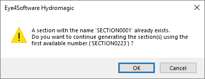
In case of numbering conflicts, Hydromagic will suggest another initial number
When a clipping area is selected, all lines will be clipped within this area. When clipping area is set to "N/A" all lines will be loaded "AS IS". To use clipping, draw a boundary first.
To start creating cross sections, just click "OK". After a few seconds you will see the imported lines in your project. The dialog box will close automatically on successful cross sections generation.
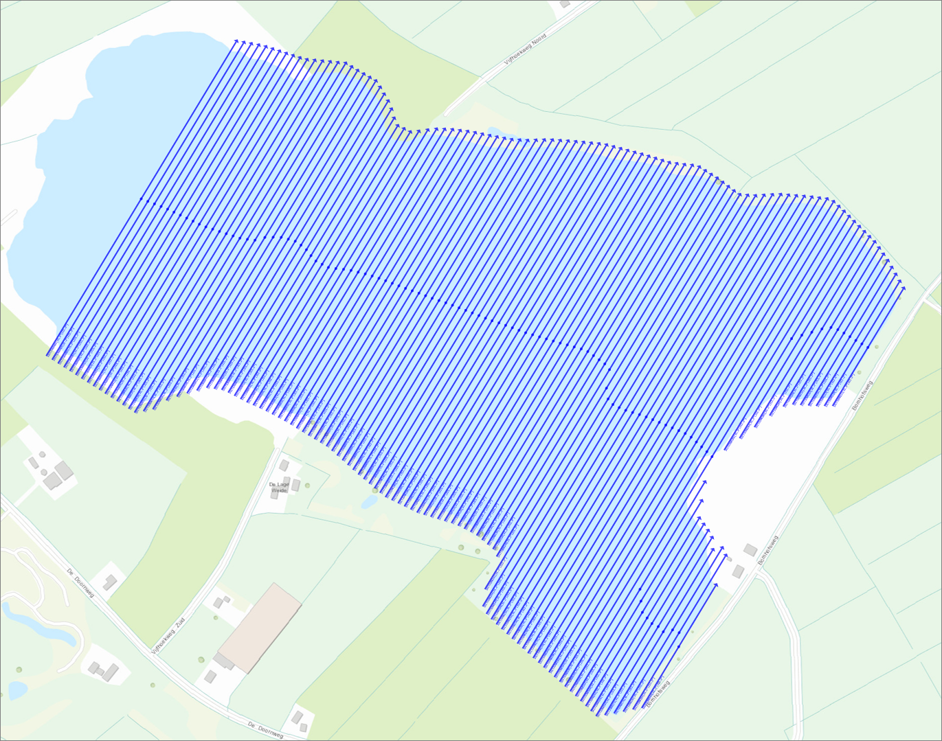
Sections generated from DXF file shown above
In Hydromagic you use cross sections for volume calculations or to define a channel design as well. When importing cross sections from an AutoCAD DXF file, Hydromagic will automatically detect whether the line contains different Z-Values. When this is the case the Z-Values are automatically stored into a cross section profile as shown below:
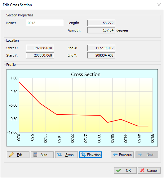
Example of an imported cross section with Z-values defined.
In order to set the Z-values of polyline vertices in AutoCAD, you need a version of AutoCAD that supports 3D. This means that these lines cannot be generated with AutoCAD LT.