
Generating a Reference Matrix from (AutoCAD) DXF map
A reference matrix that can be used to perform volume calculations can be created from:
- one or more soundings;
- shoreline information;
- collection of cross sections, also known as channel design;
- a vector chart which contain 3D vectors.
A reference matrix can also be selected in "Hydromagic Dredging" to display the maximum dredging depth together with underdredge and overdredge values.
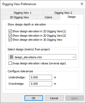
A reference matrix can be selected in Hydromagic Dredging
to display the design depth.
CAD drawing
This is perhaps the easiest way to create a reference matrix (DTM or digital terrain model), provided that an AutoCAD DXF design of the area is available (and of course, contains elevation information). From the vectors collected from the CAD file, a TIN model is generated from which heights are calculated. When comparing the matrix created from a sounding, with a matrix created from a CAD drawing, we can calculate the amount of material which has to be removed or added in order to get the result as defined in the CAD drawing (dredging volumes). A sample CAD design of how to construct a basin is displayed below:
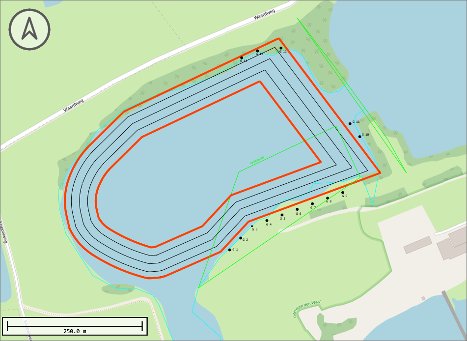
Example of an AutoCAD DXF drawing containing elevation lines.
Starting the tool
To start the conversion, make sure you have imported the CAD drawing (vector map) into the project. When it displays correctly in the map view, right-click the loaded DXF file in the 'Project Explorer' and select the 'Export to Matrix...' option. This will launch the "matrix from vector" tool. In this tool, you can select the name(s) of the layer(s) you want to include in the calculation.
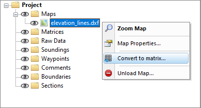
Select the "Convert to Matrix..." option from the context menu.
Using the conversion tool
Use the drop-down box to select the map layer that contains the features with the elevation information you wish to use in the matrix generation. It is recommended to draw these lines in a separate layer in your file. Click the "Select..." button to select the layers to include in the calculation.
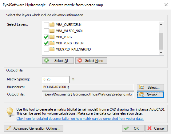
Select the DXF layers to include.
Matrix spacing
Set the required spacing. Please note that when using the volume calculation using matrices, this spacing should be equal to the one used in the matrix generated from the sounding, otherwise it cannot be used in volume calculations.
Boundaries
Select the area or boundary that will be used to indicate the clipping area of the matrix generated from the AutoCAD file. You can for instance convert the outer polyline to a boundary. When you want to disable clipping, select the default option "NONE". By selecting multiple boundaries you can also define islands.
Output file
Click the second 'Browse' button to select a folder and filename for the generated matrix. The matrix is saved as a binary file containing all the XYZ pairs calculated by this tool using a TIN model.
Starting generation
When all options have been set, click the 'OK' button to start the matrix generation process. The software will collect all usable vertices (coordinates) from the AutoCAD drawing and creates a TIN model of the data to calculate the matrix with fixed cell sizes. After generation, the matrix will be loaded and added to the project. During the generation process, a progress bar will be shown in the status bar. When finished and loaded, you will see something similar to the image below.
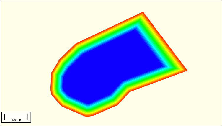
The generated matrix in 2D.
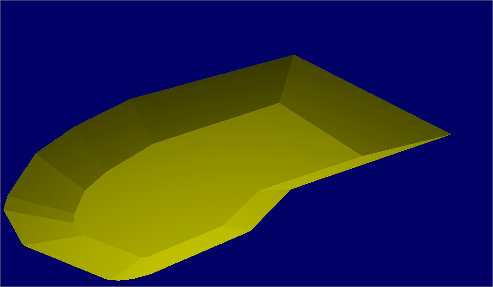
The generated matrix in 3D.
Troubleshooting
If the matrix failed to generate or display, please check the following:
- Is the AutoCAD DXF file in the same coordinate system as your project ?
- Did you select the layers containing the 3D shapes?
- Is the generated matrix visible in the 'Project Explorer'?
- Did you set the matrix color ranges ?
- Check the matrix display settings;
- Are there any errors in the "Processing" tab of the activity view ?
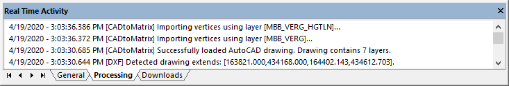
You can check the "Processing" activity view tab for errors..
Video Tutorial: Generate a matrix from DXF file(s)
The following video tutorial shows how to generate a reference matrix or DTM from a loaded (AutoCAD) DXF file.
It also shows how to create a boundary from a drawing entity.
Hydromagic allows you to generate a reference matrix an AutoCAD DXF file.